When to Choose an Electromagnetic Flow Meter, and When Not To
The short answer
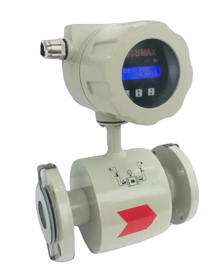
Choose an electromagnetic meter when the liquid conducts, the line runs full, and you want a full-bore instrument with nothing in the flow path — water, effluent, sewage, slurries, most acids and caustics, and nearly all water-based process liquids. Do not choose one for oils, solvents, fuels, gases, steam, or ultra-pure and demineralised water: there is no signal to measure. That is not a limitation to engineer around with a bigger transmitter. It is the physics.
How the measurement works, and why the conductivity limit exists
A coil around a lined tube establishes a magnetic field across the bore. A conductor moving through that field generates a voltage proportional to its velocity — Faraday’s law. In a magnetic flow meter the conductor is the liquid itself, and a pair of electrodes set in the tube wall picks up the induced voltage. Multiply the mean velocity by the known bore and you have volumetric flow.
Two consequences follow, and they explain most of what is good and bad about the technology.
First, the measuring section is an empty lined tube — no rotor, no bluff body, no restriction. There is no wear part in the stream, no permanent pressure loss beyond that of an equivalent length of pipe, and nothing for suspended solids to block. Slurries, sewage and mixed liquor go straight through.
Second, the liquid has to conduct, or no voltage is generated at all. Different designs place the threshold in different places — a figure in the region of 5 µS/cm is often quoted for magnetic meters in general — but you design to the number on the datasheet of the meter you are actually buying. For the Accumax electromagnetic flow meter, the datasheet specifies media as conductive liquid with electrical conductivity greater than or equal to 20 µS/cm for water.
If you cannot state the conductivity of your process liquid, measure it before specifying anything. Raw water, borewell water, treated water, effluent and cooling water sit comfortably above the threshold. RO permeate, condensate and DM water frequently do not, and they are the applications where magnetic meters get specified in good faith and then behave unpredictably at low flow.
Where the electromagnetic meter is the right call
Dirty and abrasive liquids. Sewage, mixed liquor, mineral slurries, wood pulp and heavy suspensions pass through a full-bore tube that has nothing for them to catch on. A turbine or paddle wheel in the same service is a maintenance item.
Corrosive liquids. The wetted parts are the liner and the electrodes, both selected for the duty: PTFE (Teflon) or rubber (neoprene) lining, with PTFE, hard rubber and polyurethane listed as options, and SS316L or Hastelloy C22 electrodes. Choose these for the chemistry first; the rest of the order is secondary.
Bidirectional and net-volume duties. The meter reads forward and reverse flow, with reverse indicated by a minus sign before the flow rate, and direction is configurable as forward, reverse or bidirectional. It keeps a positive totaliser, a negative totaliser and a delta totaliser equal to positive minus negative — exactly the net-volume figure a groundwater or effluent return asks for.
Liquids whose properties move. Because the induced voltage responds to velocity rather than to momentum or to a mechanical rotor, the reading is largely indifferent to density, viscosity, pressure and temperature within the meter’s ratings. A liquid that thickens on a cold morning does not shift the calibration.
Wide line-size range on one technology. 15 NB to 350 NB, with a flow measuring range of 0.2 m3/h to 1300 m3/h, means one instrument type and one spares philosophy across a plant.
Where it is the wrong call — say so early
Non-conductive liquids. Oils, solvents, fuels and unmixed hydrocarbons produce no signal. This is the single most common misspecification.
Gas and steam. Not measurable by this principle at all.
Partially filled pipes. The meter measures the velocity of what is in the tube and multiplies by the full bore area, so air is counted as liquid. There is an empty pipe alert, and the empty-pipe status can be enabled or disabled — but detecting the fault is not the same as measuring through it. Fix the hydraulics.
Coating and incrustation duties. A film building up over the electrodes changes the electrical path and drifts the reading. It is a slow, quiet error, not a failure. Scaling liquids need a cleaning regime, and the question belongs at enquiry stage.
Where suspended solids must not be counted. The meter is volumetric, so suspended matter is included in the reading. If you need the liquid phase alone, this is the wrong instrument.
Very low flow. Below a few per cent of span a low-flow cut-off is needed to suppress noise, so small flows report as zero. The cut-off here is user configurable from 0 to 10%, and so is damping time. Both are useful; neither manufactures resolution that is not there.
Comparison against the alternatives
| Electromagnetic | Turbine | Paddle wheel | Ultrasonic (transit time) | |
|---|---|---|---|---|
| Suits | Conductive liquids | Oil, solvent, diesel, chemical | Water service, retrofit | Water, non-conductive liquids |
| Conductivity needed | Yes, >= 20 µS/cm for water | No | No | No |
| Line sizes | 15 NB to 350 NB | 15 to 100 NB | From 25 NB | DN15, DN20, DN25 (AMR variant DN15-DN40) |
| Accuracy as published | Not recoverable from the datasheet copy held — ask | ±1% FS | +2% FS | Class 2/B |
| Pressure | 20 bar / 20 kg/cm2 | Up to 30 kg/cm2 | Max. 5 kg/cm2 | 1.6 MPa max working |
| Temperature | PTFE liner to 230 °C; rubber liner to 85 °C | Up to 70 deg. C | Up to 50 deg. C | Grade T30/T50/T90 |
| Moving part in the stream | None | Rotor | Impeller at the wall | None |
| Power | 85-270 VAC 50-60 Hz / 24 VDC | Not published — ask | 230 VAC / 24 VDC | 3.6 V lithium, <0.2 mW |
| Output | 4-20 mA / RS485 / pulse | 4-20 mA and RS485 | 4-20 mA and RS485 | LoRa / LoRaWAN; AMR variant adds M-Bus and RS485 |
Sources: the Accumax electromagnetic, turbine, paddle wheel and ultrasonic water meter datasheets. Note the honest gap: the accuracy row on the electromagnetic datasheet is not legible in the copy held here, so a buyer specifying against a regulatory accuracy requirement must get that figure in writing on the quotation rather than from a brochure.
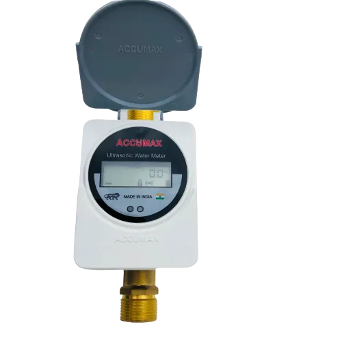
Two things the table cannot show. The ultrasonic meters run for years on a lithium cell, the natural choice where there is no mains supply — the ultrasonic AMR meter adds LoRa at 868 MHz and M-Bus/RS485 on EN1434, Modbus and CJ188. And the turbine manual requires a strainer before the sensor and periodic cleaning; that is a recurring cost of ownership the magnetic meter does not carry.
Sizing: do not size to the pipe
The most expensive magmeter error after conductivity is oversizing. The meter is specified per line size with a minimum and a maximum flow, and the datasheet notes minimum flow is in general 5% of maximum flow. Run below that and you are in the region the low-flow cut-off exists to suppress.
| Line size | Min flow (m3/h) | Max flow (m3/h) |
|---|---|---|
| 40 NB | 1.1 | 22 |
| 50 NB | 1.8 | 36 |
| 80 NB | 4.5 | 90 |
| 100 NB | 6.05 | 121 |
| 150 NB | 15.9 | 318 |
| 200 NB | 22.5 | 450 |
| 250 NB | 30 | 600 |
| 300 NB | 42.5 | 850 |
| 350 NB | 65 | 1300 |
Smaller sizes list minimum flows of 0.2, 0.3 and 0.45 m3/h for 15, 20 and 25 NB. Take the duty flow from the pump curve at the delivered head and place it in the upper part of the chosen size’s range; where it falls far below what the pipe size suggests, fit a smaller meter with reducers.
The installation decisions that make or break the reading
The instrument is only as good as the velocity profile it is given.
- 10 DN upstream to a T-connection, per the manual.
- 5 metres from a downstream gate valve — between the axis of the flow meter and the axis of the valve.
- Downstream of the pump, never upstream, to avoid vacuum.
- Vertical or inclined pipe with upward flow. This is the recommended orientation and it keeps the tube flooded. Avoid vertical pipes with a free outlet.
- On a horizontal pipe, the converter goes on the upper part — the converter, or the junction box on the separate version. The electrodes should sit on the horizontal diameter so that entrained air running along the top of the pipe does not sweep across them.
- Earthing is part of the measurement, not part of the wiring. The meter has a built-in grounding electrode as a third electrode. On plastic pipelines and lined metal pipes, grounding rings at both ends are the optional route — and the manual is clear that grounding rings are not included in the delivery. If your line is plastic or fully lined, put them on the purchase order.
Certification and hazardous areas
The datasheet’s key features name flameproof and weatherproof construction and function in a potentially explosive atmosphere, quoting IS/IEC 60079-1:2007 and IS/IEC 60079-0:2004. ISO 4064:2014 appears under other approvals, and the meter is wet calibrated at an IEC/ISO/EN 17025 accredited calibration laboratory.
No certificate or approval number is shown against the 60079 entries. If your site requires a specific zone, gas group and temperature class, ask for the certificate and its number against the model supplied — a standard named in a features list is a design claim, and an area classification file needs the certificate itself.
What comes out of the meter
Outputs are 4-20 mA, RS485 and pulse, ordered individually through the ordering code, with 1.4 kV isolation between input, output and power supply. On RS485 the meter runs Modbus at 2400 to 38400 baud with selectable parity, stop bits and output format. The low and high flow alarm is an open-drain output taking a maximum 50 mA DC; the pulse output takes a maximum 80 mA at a 10 ms pulse width. The display is a 16x2 LCD, integral or remote up to 10 m of cable, resolving flow to 0.01 L/min or 0.01 m3/h with a 10-digit totaliser.
Where the reading is needed away from the pipe, the remote indicator is the RS485 secondary display; where several meters must be logged together, the data logger for flow meter takes up to 15 devices over Modbus RS485 to .CSV files on an SD card. For groundwater abstraction reporting, the digital flow meter with telemetry system is the built to CGWA guidelines route.
The five questions that settle the decision
- What is the conductivity of the liquid, measured rather than assumed?
- Will the pipe be full at the meter under every operating condition, including pump-off?
- What is the actual duty flow at the delivered head, and where does it fall in the size’s min-max range?
- What liner and electrode does the chemistry need, at the temperature the process actually runs?
- What accuracy and repeatability figure will be stamped against this serial number, and from which accredited laboratory is the wet calibration certificate coming?
Answer those before comparing prices. Four of the five change which instrument you should buy.