Flow Meters and CGWA Groundwater Monitoring Guidelines
If you hold a CGWA No Objection Certificate for groundwater abstraction, the equipment side of the obligation comes down to four things: a flow meter of specified technology and accuracy on the borewell discharge, tamper-evident sealing of that meter and its electronics, a telemetry link pushing cumulative abstraction data to a secure cloud on a defined schedule, and data available to you and the authority without anyone visiting site.
What follows is what CGWA is, why the metering condition exists, and what the guideline specification asks the hardware to do. Where the specification is silent or the extract incomplete, that is stated rather than filled in.
What CGWA is and why it exists
The Central Ground Water Authority is a statutory body constituted under the Environment (Protection) Act and functioning under the Ministry of Jal Shakti. Its role here is straightforward: groundwater in much of India is drawn faster than it recharges, and until abstraction is measured it cannot be managed. CGWA issues No Objection Certificates to industrial, infrastructure and mining projects that draw groundwater, and sets the technical specification for the meter installed against that permission.
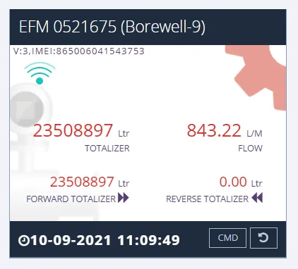
The practical consequence is that abstraction stops being a self-declared number. Once a telemetry meter is installed to the guideline, cumulative forward volume, reverse volume, net volume and pump running hours are timestamped at source and sent to a cloud the authority can read. The compliance timeline, and any date by which installation must be confirmed back to the authority, is set out in the conditions attached to your own NOC — read that document rather than a general summary.
Note the wording used here: equipment is built to CGWA guidelines. No CGWA certification scheme is being claimed and no certificate is evidenced.
What the guideline asks of the meter itself
| Requirement | Specification as written |
|---|---|
| Metering technology | Ultrasonic or electromagnetic |
| Turndown ratio | 10 or above |
| Accuracy | Better than ±2% over the operating range, 10% to 100% of maximum flow rate |
| Calibration laboratory | Testing or calibration at an ISO 17025:2017 accredited laboratory |
| Calibration points | At least 4-point calibration, at 10%, 40%, 70% and 100% of rated flow |
| Magnetic field immunity | Performance unaffected by an external magnetic field, as specified in ISO 4064 |
| Mounting plane | Accuracy retained in horizontal and/or vertical planes |
| Manufacturing standard | Preferably manufactured as per ISO 4064:2014 |
| Ingress protection | IP68 |
| Body material | Brass, bronze, MS, SS or engineering plastic, compact enough to avoid tampering |
| Indicator cover | Sturdy glass, PP or PC; straight reading type; not removable if the protective glass is broken |
| Body markings | Make/brand, size/nominal diameter, serial number and year of manufacture, metrological specifications |
| Sealing | Mechanical and electronic (software) sealing; any attempt to open the meter or enclosure should physically damage the tag |
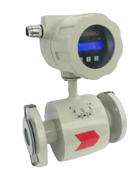
Two rows decide the order. The technology row rules out turbine, paddle wheel and differential-pressure meters entirely — the choice is between an electromagnetic flow meter and an ultrasonic one, and on a borewell discharge carrying normal groundwater either is viable. The accuracy row is written against the operating range, 10% to 100% of maximum, not against full scale at one point, which is why the turndown of 10 or above sits alongside it. An oversized meter runs near the bottom of its range and struggles to hold the specification where it spends its time. Size to the pump duty, not to the pipe you happen to have.
Line sizes and flow ranges
The Accumax specification for its digital flow meter with telemetry system lists these ranges, other line sizes available:
| Line size | Flow range |
|---|---|
| DN40 | 0.25 lps to 5 lps |
| DN100 | 3 lps to 30 lps |
| DN150 | 13 lps to 130 lps |
Match the pump’s rated discharge against these before assuming the meter matches the existing pipe diameter. Reducing to a smaller meter size to bring the duty into the middle of the range is normal practice, and cheaper than failing an accuracy check at low flow.
Telemetry: what has to reach the cloud, and how often
This is what most separates a CGWA-specification meter from an ordinary industrial one. The requirement is not that the meter can talk, but that a defined set of parameters arrives on a defined schedule at a cloud with defined provenance.
Parameters transmitted to the secure cloud:
- Timestamp
- Cumulative forward flow volume
- Cumulative reverse flow volume
- Cumulative net volume
- Cumulative pump working hours
- Meter serial number
- Device last calibration date
- Borewell ID, as provided by CGWA
How the link must behave:
| Requirement | Specification as written |
|---|---|
| Communication type | LAN for internet connectivity, or LoRa WAN and/or cellular GPRS |
| Transmission frequency | Minimum 2 times in a day |
| On-board logging | Daily flow data with a timestamp, retained at least 2 years and sent to the cloud by telemetry |
| Store and forward | If telemetry is non-functional through power cut or weak signal, the meter stores the data and transmits once telemetry is live |
| Loss of communication | Indicated in the server within 48 hours |
| Encryption | Communication shall be encrypted to avoid tampering |
| Cloud service provider | Empanelled with the Ministry of Electronics and Information Technology (MeitY) |
| Electrical environment | Must function in electrically noisy environments and near high-voltage power lines |
| Configuration | Configurable either using the DTU or from the server |
The store-and-forward clause is the one to test at commissioning rather than trust. Rural borewell sites lose mains power and cellular signal, often together, and a meter that keeps metering but silently drops unsent readings produces a compliance gap nobody can reconstruct. Ask for a deliberate power-cut and signal-loss test, and confirm the backlog uploads with its original timestamps rather than the reconnection time.
The MeitY empanelment condition applies to the cloud provider, not the meter. If a vendor’s dashboard is hosted elsewhere, the hardware can be perfect and the arrangement still fails the condition. Ask which cloud the data lands in.
Power, because most field failures are power failures
| Requirement | Specification as written |
|---|---|
| Meter power | Battery operated or UPS powered, with power-OFF detection |
| Telemetry unit power | Battery or external supply; metering data must remain stored in the meter even if telemetry is off due to power failure |
| Battery life | At least 3 years at 2 transmissions per day, replaceable without any data loss; not applicable for UPS supply |
| Battery monitoring | Battery usage indicated at the server |
Note the phrase “replaceable without any data loss”. A battery change that resets a cumulative totaliser breaks the continuity of the abstraction record, which is the entire point of the installation. Confirm the replacement procedure before the first battery is due.
Alarms, tamper detection and reverse flow
| Capability | Specification as written |
|---|---|
| Detection | Capable of detecting leak, zero (no) flow and high flow |
| Reverse flow | Detected and recorded separately |
| Tamper alarm | Alarm reported to the server as and when tampered |
| Real-time alarms | Battery and tamper alarms communicated in real time |
| Timestamping | All water meter readings time stamped |
Reverse flow is recorded separately rather than netted off silently, which is why the transmitted list carries forward, reverse and net volumes as three figures. On a borewell with a non-return valve the reverse total should stay at zero; a rising one is a maintenance signal worth acting on.
Installation conditions that decide whether the data is defensible
| Requirement | Specification as written |
|---|---|
| Location | Installed at the borewell pump discharge line, before any branching |
| Bypass | No bypassing of pipe prior to the installed flow meter |
| Full flow | The pipe must be full of water at all times, with sufficient upstream and downstream straight length |
“Before any branching” is unambiguous and is the most common site failure. A tee ahead of the meter — even one for something harmless like a wash-down point — means abstraction is passing unmetered, and it is visible on the drawing to anyone inspecting.
The guideline document refers to a figure for upstream and downstream straight lengths rather than stating distances in text, so no numeric requirement is reproduced here. Ask your supplier for the straight-length figures against your line size in writing, and get them onto the piping drawing before fabrication.
The data management software side
The guideline treats the software as part of the deliverable, not an accessory:
- Cloud based with web portal access, so a user can view data through a browser; it may additionally be installed on a server in a central database or control room.
- Consumer, engineer and manager screens available separately.
- Database backup and restore, real-time data access, web-enabled operation, and alerts to the user by email or SMS.
- Capability to add customer information and create customisable data fields.
Accumax’s own note in the specification document is that it “provides Cloud Computing Technology which is far better than this mentioned specifications”. That is the manufacturer’s characterisation. What to do with it is to ask for a demonstration login on a live installation of comparable size, and to check the export format your compliance team will have to work with.
Water level recording, and an open question
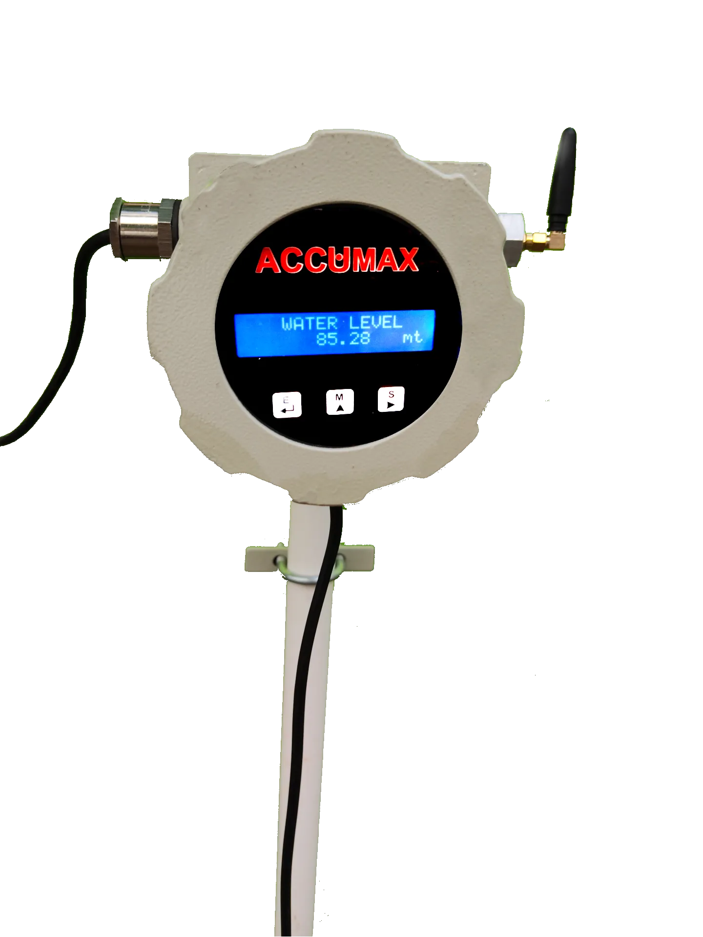
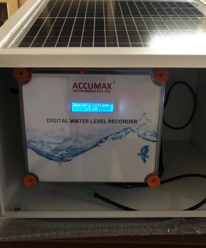
Groundwater NOC conditions commonly pair abstraction metering with water level observation, so drawdown at the abstraction structure is visible alongside volume drawn. Accumax lists a piezometer digital water level recorder built to CGWA guidelines for borewells, with an IP68 sensor and optional telemetry, and a solar powered digital water level recorder with telemetry which calculates water level from hydrostatic pressure and records groundwater level, water temperature, atmospheric pressure and atmospheric temperature. Its logged fields are date, time, corrected and raw water level, water temperature, atmospheric pressure, atmospheric temperature and battery voltage, written to an SD card in CSV format and transmitted to a server at preset intervals.
What the specification extract quoted here does not contain is a numbered water-level specification equivalent to the metering one — range, accuracy, logging interval and reporting frequency for the level recorder are not set out in it. If your NOC imposes a water level condition, get those figures in writing and check them against the wording of that NOC, not against the flow meter specification.
A checklist to take into the vendor call
- Which technology is proposed, electromagnetic or ultrasonic, and why for this borewell.
- The pump’s rated discharge, and where it sits in the meter’s 10-to-100% operating range.
- A calibration certificate from an ISO 17025:2017 accredited laboratory, at 10%, 40%, 70% and 100%.
- The name of the cloud provider and confirmation of MeitY empanelment.
- A witnessed power-cut and signal-loss test showing store-and-forward with original timestamps.
- The battery replacement procedure, and written confirmation that totaliser data survives it.
- The upstream and downstream straight-length figures for your line size.
- The sealing arrangement, and what a broken seal looks like on the server.
Published product specifications are pending engineering sign-off, so confirm every figure above against the datasheet revision quoted for your order — and confirm the guideline text against the current version of the authority’s own specification, which is the document that governs, not a vendor summary of it.