How to Install a Piezometer in a Groundwater Observation Well
What a piezometer is, in one paragraph
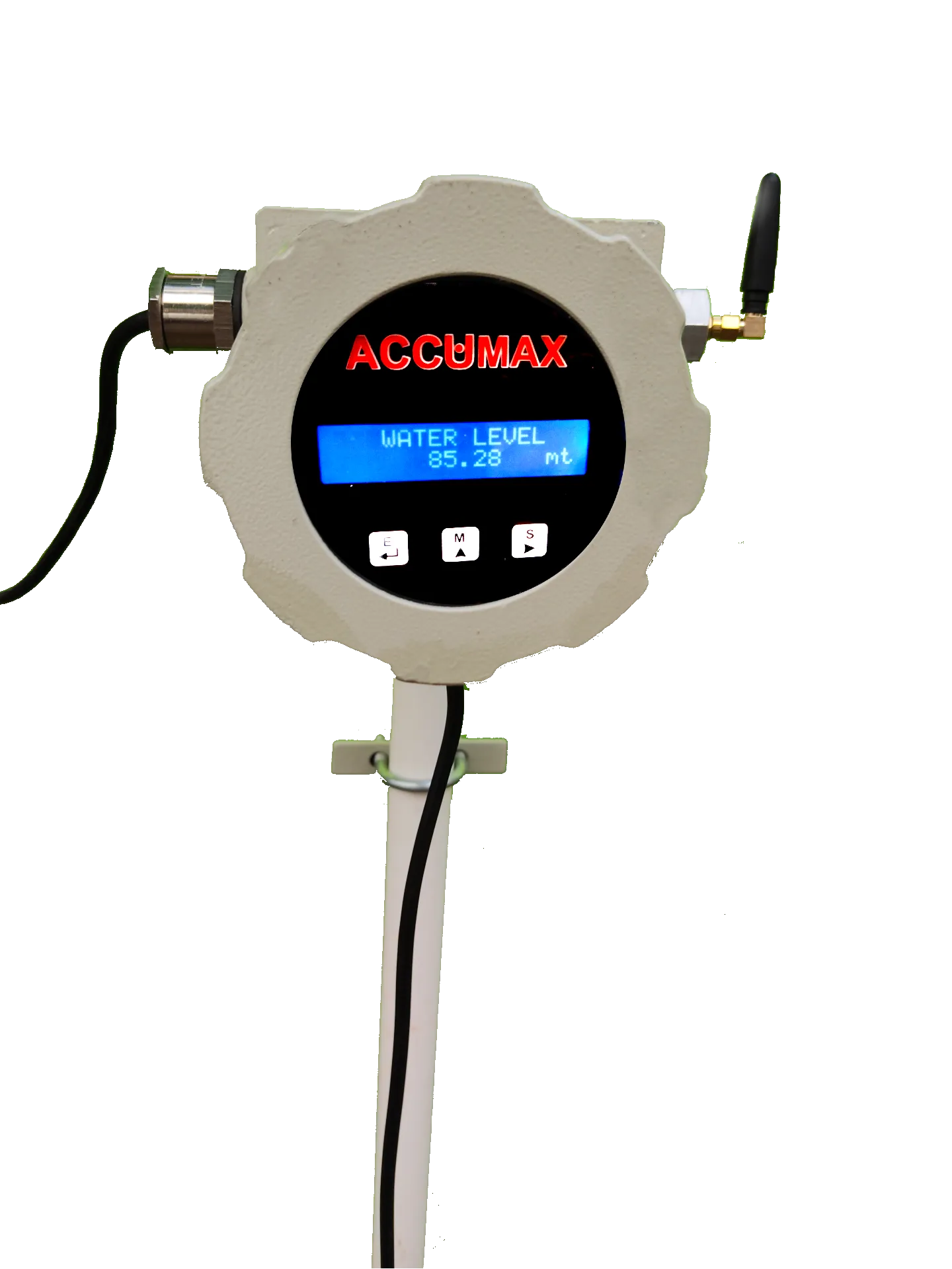
A piezometer used for groundwater monitoring is a sealed pressure sensor on a cable, hung in a dedicated observation well below the lowest water level you ever expect to see. It measures the head of water standing above it, and the recorder converts that head into a water level and stores it with a timestamp. Add local storage and a modem and the same assembly is sold as a Digital Water Level Recorder (DWLR). It measures nothing about abstraction — the flow meter on your discharge line does that. The piezometer answers the other question: what your pumping is doing to the aquifer, and whether it recovers between pumping cycles.
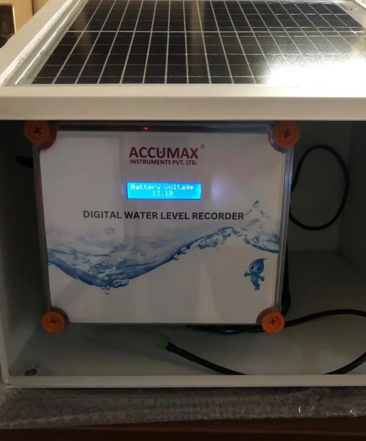
The Accumax Piezometer / DWLR is built to CGWA guidelines and offered in telemetry and non-telemetry versions, with an IP68 sensor, an IP66 display enclosure, a universal 85-300 VAC / 24 VDC supply and sensor cable supplied to the length the borewell requires. For unmanned outdoor sites there is the solar powered digital water level recorder with telemetry, which calculates water level from hydrostatic pressure analysis and logs groundwater level, water temperature, atmospheric pressure and atmospheric temperature together.
Why groundwater regulation asks for an observation well
A flow meter records how much you took. It says nothing about whether the aquifer can sustain it. The observation well supplies the missing half of the record: a continuous water-level series beside your abstraction point, so that drawdown during pumping and recovery after pumping are both visible in the data rather than asserted in a covering letter.
This is also why the observation well has to be a separate hole. A borewell that is pumping shows you the level inside its own cone of depression, dominated by well losses and the pump’s hydraulics. It is not the aquifer level. A piezometer set at a distance in an undisturbed hole is.
The distance most commonly quoted for the observation well is a minimum of 50 metres from the abstraction borewell. Treat that as a starting point, not as the rule: the number of piezometers, their depth, their spacing and the reporting interval are conditions written into your NOC. Read the NOC and, where it is silent, ask the authority in writing before you drill. The same applies to the abstraction threshold at which a piezometer becomes a condition at all — a figure of the order of 10 m3 (10,000 litres) per day is widely quoted, but the trigger varies by category of user and by state authority.
Three numbers to settle before you order the instrument
Cable length is not a field decision. It is fixed at manufacture, and getting it wrong means either a sensor dangling above the water in May or a coil of surplus cable in a terminal box for the next ten years.
| What to establish | Why it decides the order | How to get it |
|---|---|---|
| Total depth of the observation well | Sets the maximum possible sensor setting depth | Driller’s log, measured after development, not the tender depth |
| Lowest water level you expect | The sensor must stay submerged at the seasonal minimum, in a drought year, with the pump running | Historic dips for the area plus your own drawdown test |
| Sensor setting depth below that minimum | Determines cable length and the pressure range the sensor must cover | Setting depth plus casing stick-up plus routing to the enclosure |
Add 5 to 10 metres of cable beyond the calculated figure. Water levels move between seasons and between years, and a sensor that has to be lowered further in three years’ time is otherwise a new purchase. Accumax supplies the sensor cable to the required length; no maximum length is published, so state your depth explicitly on the enquiry and have it confirmed on the order acknowledgement.
Where the sensor actually hangs
Two constraints fight each other. The sensor must be deep enough to stay submerged in the driest month you can imagine, and shallow enough that it is not sitting in the silt that accumulates at the bottom of every observation well. Set it a few metres above the base of the well and comfortably below the seasonal minimum, and keep the number written down — every level the instrument reports is referenced to it.
Everything above the water matters too. The cable should hang free rather than rub against the casing, and should be clamped at the wellhead so its weight is carried by the clamp and not by the sensor’s cable gland. The terminal box goes above ground on the casing or a nearby post: dry, clean, shaded and lockable.
Installation, step by step
1. Site and drill the observation well. Locate it after a proper survey, at the distance and depth your NOC specifies, in ground that will not be built over, parked on or bunded off in two years. Case and develop the well properly — an undeveloped hole silts up and the record degrades with it.
2. Fix a datum and write it down. Choose one permanent, unambiguous reference point, normally the top of the casing, and mark it physically. Record its height above ground level and, if the survey exists, its reduced level. Every reading the instrument produces is a depth below this mark. If the casing is later cut, extended or replaced, the entire series before that day is referenced to a datum that no longer exists.
3. Take a manual dip before anything electrical goes down the hole. Use a dip meter from the marked datum and record the static water level, the date and the time. This is your independent check, and the only one you get for free.
4. Take the zero reading of the piezometer. With the sensor still in air, note what the instrument reads. It tells you the offset you are starting from, and it is the reference you come back to when a reading later looks wrong.
5. Lower the sensor. Pay out the cable steadily and mark the cable at the datum when the sensor reaches its setting depth, so the depth can be reproduced by anyone after you. Watch the display as it goes down: the reading changes as soon as the sensor enters water, which confirms both submergence and a working cable and transmitter before you close everything up.
6. Clamp, route and terminate. Secure the cable at the wellhead. Route it to the enclosure with a drip loop so that water running down the cable does not run into the gland. Land the sensor and supply into the terminal box, keep the box clean and dry, and close it.
7. Configure the recorder. On the telemetry recorder, the depth of sensor, the pressure sensor selection, the logging intervals and an error compensation figure are all set parameters — over RS485 from the desktop application, using a USB-to-RS485 converter onto the device A and B wires. Set the sensor depth to the figure you actually used in step 5, not the design figure.
8. Verify against a second manual dip. Dip the well again from the same datum and compare it with what the instrument reports. Any difference is your commissioning offset. Resolve it now, in writing, rather than discovering it in a quarterly return.
Barometric pressure, and why the raw reading is not the reading
A submerged pressure sensor reads the water above it plus whatever the atmosphere is pressing down on the water surface. Barometric pressure moves by tens of millibars with weather, which is tens of centimetres of apparent water level — enough to swamp the trend you are trying to observe on a slow-moving aquifer. Non-vented sensors therefore need the atmospheric term removed.
This is why the Accumax telemetry recorder measures atmospheric pressure with an on-board barometer module and logs both figures side by side. Its data fields are Date, Time, Corrected Water Level (Mtr), Raw Water level, Water Temp (C), Atm Press (Bar), Atm Temp (C) and Batt Volt. Keep the raw column. When a corrected series looks implausible, the raw level and the barometric column together tell you whether the water moved or the weather did.
Telemetry, or a card somebody collects
Both work. They fail differently.
| Non-telemetry | Telemetry | |
|---|---|---|
| How data leaves site | Read at the instrument, or over the data interface supplied — confirm the download route with the supplier for the non-telemetry build | GSM to the server at preset intervals; Wi-Fi and SD card also available on the solar unit |
| You discover a fault | On the next visit | When the series stops arriving |
| Site requirement | Access, and someone who will actually go | Network coverage at the wellhead, and power |
| Typical fit | Compact sites, staffed plants | Remote wells, multiple wells, regular reporting obligations |
On the solar-powered unit the data can be pulled three ways: transmitted to the server over GSM at preset intervals for login and download, fetched over Wi-Fi from the SD card by joining the device’s own network (SSID TDWLR-[Hardware ID], page at tdwlr.local or 192.168.4.1), or read straight off the SD card as .CSV. Whichever route you plan to use, prove it on the day of commissioning while the installer is still on site.
Power, and the failure nobody plans for
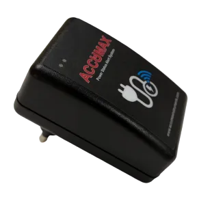
The recorder is only as continuous as its supply. The mains version takes 85-300 VAC or 24 VDC; the solar version runs from a rechargeable battery charged by its panel, with a 12 V DC supply module feeding the device +V and GND terminals. Battery voltage is one of the logged fields — chart it. A slow decline in Batt Volt over a fortnight is a panel shaded by a new structure or coated in dust, visible long before the data gap that would otherwise be your first warning. Where mains supply is unreliable, a power failure SMS alert device closes the same gap for the mains-powered instruments beside it.
What to keep on file
Keep the driller’s log and well development record, the datum description and its height, the sensor setting depth, the commissioning manual dip with date and time, the configured logging intervals and the instrument serial number. When a return is queried, this is the file that answers it. Reconstructing it two years later from memory is not possible.
Questions to put to your supplier
Some things a datasheet does not settle, and a buyer should ask before the order rather than after:
- What pressure range is the sensor being supplied with, and what is its accuracy and long-term drift specification? No accuracy figure is published for either recorder, so get it in writing on the quotation.
- What is the maximum cable length available for the depth you have?
- What is the operating temperature band of the enclosure as it will be mounted at your site?
- Which network does the telemetry unit use at your location, and what happens to the data during an outage?
- What does recalibration involve, who performs it, at what interval — and does it require the sensor to come out of the well?