Installing a Telemetry Flow Meter to CGWA Guidelines
Where the meter goes, and where it must not
On a borewell abstraction line the meter goes in the pump discharge line, before any branching. Nothing may tee off upstream of it, there must be no bypass around it, the pipe at the meter must be full of water at all times, and sufficient upstream and downstream straight length must be provided.
Those four requirements are written into the CGWA guideline document Accumax works to, and an inspector can check all four by walking the line. The practical consequence is that you site the meter first and design the manifold around it. A meter after the first tee measures part of the abstraction; a meter with a valved bypass measures whatever the operator allows. Both invalidate the record retrospectively, not merely from the day of the inspection.
Keeping the pipe full
Full-pipe operation is the requirement most often got wrong, because it is a hydraulics problem rather than an instrumentation one. A meter on a horizontal run that drains back when the pump stops reports an air-water mixture as if it were water. Three arrangements solve it:
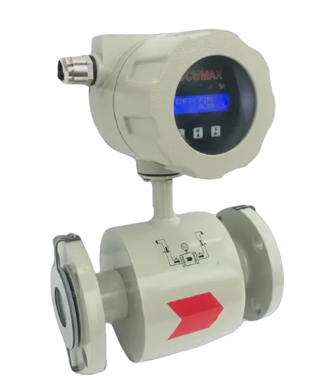
- A rising vertical section with upward flow. Water fills the tube from the bottom and cannot drain past the meter. This is the recommended orientation for the electromagnetic flow meter, which asks for a vertical or inclined pipe with upward flow direction.
- A U-bend with the meter at the bottom of the U. Where the line is otherwise horizontal and prone to draining, a low point keeps the measuring section flooded between pump cycles — the standard fix on headworks with a free-discharge delivery.
- Never a vertical pipe with a free outlet. The Accumax electromagnetic meter manual warns against this specifically: a downward pipe discharging to atmosphere will not stay full whatever is upstream.
One further rule is about not destroying the instrument: install the sensor downstream of the pump, never upstream. A meter on the suction side sees vacuum conditions the liner is not designed for.
Straight run: what the guideline says and what the meter needs
The CGWA guideline text states that sufficient upstream and downstream straight length shall be provided, then refers the reader to a figure rather than giving numbers, so no straight-run figures can be quoted from it here. Ask the authority or the supplier for the figure that applies to your meter, and get it in writing before the pipework is fabricated.
What can be quoted are the installation requirements the meters themselves carry. For the Accumax electromagnetic meter and the turbine flow meter, the manuals state a 10 DN distance upstream of the meter to a T-connection, and 5 metres between the axis of the flow meter and the axis of a gate valve located downstream. The paddle wheel flow meter brochure recommends a straight run of 10 and 5D on the upstream and downstream respectively.
Where a bend, a valve or a pump discharge sits closer than the meter asks for, the meter still reads — it reads a distorted profile, and the error is not random. It sits in the same direction every day, in a record you submit to a regulator. Design the straight run in.
Sizing the meter to the flow, not to the pipe
Line size is what the pipe happens to be; meter size is what the flow needs. On a borewell line these are often different, because the delivery pipe was sized for head loss over a long run and the duty flow sits near the bottom of that pipe’s range.
The guideline sets a turndown ratio of 10 or above and requires accuracy better than ±2% for the operating flow range, defined as 10% to 100% of maximum flow rate. Read those together: below 10% of the rated maximum, the accuracy specification does not apply. An oversized meter running a pump at 6% of span is out of specification by design, whatever its certificate says.
The line sizes and flow ranges quoted for the digital flow meter with telemetry system are:
| Line size | Flow range (lps) | Equivalent (m3/h) |
|---|---|---|
| DN40 | 0.25 to 5 lps | 0.9 to 18 |
| DN100 | 3 to 30 lps | 10.8 to 108 |
| DN150 | 13 to 130 lps | 46.8 to 468 |
Other line sizes are available. The m3/h column is a straight conversion for convenience, not a separately published figure.
Take the pump’s duty point from its curve at the actual delivered head, not from the nameplate, and check it lands in the upper two-thirds of the chosen size’s range. If it falls below 10% of maximum, reduce the meter and use reducers either side, with the straight run measured from the reducer.
What the meter has to be, mechanically
| Requirement | Specification |
|---|---|
| Metering technology | Ultrasonic or electromagnetic |
| Manufacturing standard | Preferably manufactured as per ISO 4064:2014 |
| Ingress protection | IP68 |
| Body material | Brass / bronze / MS / SS / engineering plastic, compact enough to avoid tampering |
| Indicator cover | Sturdy glass / PP / PC, straight reading type; the indicator cannot be removed if the protective glass is broken |
| Magnetic field immunity | Not affected by external magnetic field, as specified in ISO 4064 |
| Mounting plane | Must retain accuracy installed horizontally and/or vertically |
| Body markings | Make/brand, size/nominal dia., serial number/year of manufacture, metrological specifications |
| Sealing | Mechanical and electronic (software) sealing; any attempt to open the enclosure should physically damage the tag |
IP68 is not decoration on a borewell headworks. These installations flood — in a valve chamber, in a monsoon, under a leaking gland — and it is the difference between an event and a replacement.
Calibration and the paperwork that travels with the meter
Testing or calibration shall be performed at an ISO 17025:2017 accredited laboratory, with at least 4-point calibration at 10%, 40%, 70% and 100% of maximum or rated flow. The device’s last calibration date is one of the parameters the meter transmits to the cloud, so it is not a certificate that sits in a drawer — it is a field in the record the authority sees. Ask for the certificate against the serial number of the meter actually being shipped, showing the four points, before it leaves the works. A certificate issued for a model is not the same document.
Power at a borewell head
The guideline requires the meter to be battery operated or UPS powered with provision for power-off detection, and the telemetry unit to be battery operated or externally powered. A battery must last at least 3 years with 2 transmissions per day, be replaceable without any data loss, and its usage has to be indicated at the server — so depleted batteries are meant to be visible before the data stops, not after.
Critically, metering data must be stored in the meter even if the telemetry system is off due to power failure. Metering and transmission are separate power domains, and only one of them is allowed to fail quietly.
Connectivity, and what the telemetry has to do
| Requirement | Specification |
|---|---|
| Communication | LAN (for internet connectivity) or LoRa WAN and/or cellular GPRS |
| Transmission frequency | Minimum 2 times in a day |
| Store and forward | On power cut or weak cellular signal, the meter stores data and transmits once telemetry is live again |
| Loss of communication | Indicated in the server within 48 hours |
| On-board logging | Daily flow data with timestamp, for at least 2 years |
| Encryption | Communication shall be encrypted to avoid tampering |
| Cloud provider | Should be empanelled with the Ministry of Electronics and Information Technology (MeitY) |
| Electrical environment | Must operate in electrically noisy environments with EMI, and near high voltage power lines |
| Configuration | Configurable either using the DTU or from the server |
Survey the signal at the exact wellhead before committing to cellular, with the antenna where it will actually be mounted — inside a steel valve chamber is a different radio environment from standing beside it with a phone. Where coverage is marginal, store-and-forward saves the record, so test it: pull the antenna, run the pump, restore it, and confirm the missing interval appears on the dashboard.
What the meter sends, and what it must detect
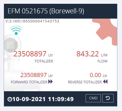
The parameters transmitted to the secure cloud are: timestamp, cumulative forward flow volume, cumulative reverse flow volume, cumulative net volume, cumulative pump working hours, meter serial number, device last calibration date, and the borewell ID provided by CGWA.
Two deserve attention at commissioning. Reverse flow is recorded separately and the meter must detect it, so a non-return valve that passes will show. And the borewell ID is issued by the authority: a meter reporting under a blank or default ID is a meter whose data cannot be matched to your NOC.
The meter must also detect leak, zero (no) flow and high flow, report a tamper alarm to the server when tampered, and communicate battery and tamper alarms in real time. All readings must be time stamped.
Commissioning sequence
- Confirm serial number, size and calibration certificate against the order before installation.
- Fit the meter before any branching, with the specified straight run and orientation; confirm no bypass exists.
- Earth and bond the meter as the manual requires for the technology supplied.
- Energise and check the display reads zero with the pump off and the line full.
- Run the pump and check the indicated rate against the pump curve at the delivered head. A gross mismatch here is nearly always air, partial filling or a straight-run violation, not a faulty meter.
- Note the forward, reverse and net totalisers with the date and time.
- Configure the borewell ID, transmission interval and server details; confirm the first two transmissions arrive.
- Test the loss-of-communication and restore path as described above.
- Apply and photograph the mechanical seals, and record the seal numbers.
- Hand over: certificate, seal photographs, commissioning totalisers, configuration record and dashboard login.
What the authority expects to see on site
An inspection is a physical check against the same short list: the meter is on the discharge line before any branching, there is no bypass, the seals are intact, the display is readable and matches the server, the serial number matches the certificate, and the borewell ID on the dashboard matches the NOC. Where a site fails, it usually fails on the manifold — a tee, a bypass, or a meter moved during a later pump change and never re-sealed.
That last one deserves a standing instruction to your maintenance contractor: if the meter comes out of the line for any reason, the seals must be reapplied and the event recorded. A broken seal with no paperwork behind it reads as tampering.
Questions the guideline does not answer
Settle these in writing before the order:
- The exact upstream and downstream straight-run lengths for your meter and line size, since the guideline text refers to a figure rather than stating numbers.
- The accuracy figure and turndown stamped against your specific meter and serial number.
- Whether the cloud service offered is on a MeitY-empanelled provider, and where the data resides.
- Who owns the data and the dashboard account if you change supplier.
- The recalibration cycle, who performs it, and whether the meter must come out of the line.