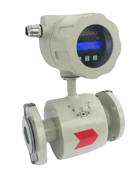
Working Principle of Electromagnetic Flow Meters
An electromagnetic flow meter works by Faraday’s law of induction. A magnetic field is applied across the metering tube; conductive liquid moving through that field behaves as a moving conductor and generates a potential difference perpendicular to both the field and the flow. Electrodes in the tube wall pick that voltage up, the converter turns it into a velocity, and velocity multiplied by the known cross-sectional area of the bore gives volumetric flow.
The working relationship is usually written as:
E = k · B · D · V
- E — induced voltage, linear with velocity
- k — proportionality constant
- B — magnetic field strength (coil excitation)
- D — distance between the electrodes, effectively the bore
- V — velocity of the process fluid
Everything else about specifying a magnetic meter — liner, electrode alloy, grounding, conductivity, empty-pipe handling — comes out of that equation and what it needs to hold true.
Why the equation matters in practice
Three of the five terms are fixed at manufacture: bore D by the line size, constant k by geometry, and field B by the coil and its excitation, which the converter holds stable. A magnetic meter’s calibration is therefore a property of the tube and coil assembly, not of the liquid.
That leaves V, and it is the mean velocity across the electrode plane, not the peak velocity in the centre. This is why installation matters: swirl or a distorted profile from a bend or half-open valve immediately upstream changes the relationship between what the electrodes see and what is passing through the pipe. The physics is exact; the velocity-profile assumption is what you can break.
It is also why the meter is inherently bidirectional — reverse the flow and the sign of the induced voltage reverses. The Accumax electromagnetic flow meter reads forward and reverse, marking reverse with a minus sign, direction configurable as forward, reverse or bidirectional. It keeps a positive totaliser, a negative totaliser and a delta totaliser equal to positive minus negative — what any line with possible backflow needs when the net figure is reported.
Why conductivity is the first thing to check
The liquid is the conductor in the circuit. If it does not conduct there is no induced voltage to measure, and no electronics will rescue the reading. That is the one absolute limitation of the principle, and why a magnetic meter cannot measure oils, solvents or diesel at all.
The Accumax electromagnetic flow meter is specified for conductive liquid at 20 µS/cm or above for water. In practice:
| Liquid | Typical position against a conductivity limit |
|---|---|
| Raw and treated water, borewell water, effluent, sewage | Comfortably above; a normal application |
| Acids, caustics, salt-bearing process liquids | Well above; the constraint is chemistry, not conductivity |
| Slurries with a conductive carrier | Above; the carrier fluid conducts |
| Demineralised water, RO permeate, condensate | Frequently below; measure first |
| Oil, diesel, solvent | Not measurable by this principle |
A bench conductivity reading on a real sample is the cheapest de-risking step in the whole selection. Conductivity rises with temperature, so take the reading at the coldest condition the line will see — that is the worst case for a magnetic meter.
The liner: what it does and how it is chosen
The liner has two jobs. Electrically, it insulates the liquid from the metal flow tube so the induced voltage reaches the electrodes instead of shorting through the pipe wall. Mechanically, it is the wetted surface, so it takes the chemical attack and the abrasion.
The Accumax meter is offered with PTFE (Teflon) or rubber (neoprene) liners, customisation options listed as PTFE, hard rubber and polyurethane. Published medium temperature range is -10 (0) °C to +200 °C with a remote display, and the liner sets the practical ceiling: PTFE up to 230 °C, rubber up to 85 °C.
In general engineering terms, PTFE is the broad-chemistry answer — acids, caustics, solvents, high temperature — but comparatively soft against abrasive solids. Hard rubber and polyurethane are the abrasion answers for sand-bearing or grit-laden duty, at the cost of temperature ceiling and chemical range. Where a duty is both hot and abrasive, put that tension to the manufacturer rather than resolving it from a catalogue.
Electrode material is a chemistry decision, not a formality
The electrodes sit in direct contact with the liquid and must pick up a very small voltage without corroding, passivating or fouling. The Accumax meter lists SS316L and Hastelloy C22, with SS316L and Hastelloy C in the ordering code.
SS316L is the general-purpose choice for water, effluent and mild process duty. Hastelloy C22 is the upgrade for aggressive chemistry — strong acids, chlorides, oxidising media — where stainless would be attacked. Getting this wrong rarely shows up as a failure; it shows up as slow drift as the electrode surface changes, which is much harder to diagnose. If the chemistry is unusual, have the electrode material nominated against your specific media.
Coating is the other failure mode: greasy or oily effluent films over an electrode and insulates it from the liquid. That is a cleaning and access question, worth designing for at installation, since the body is flanged and coming out of the line is not quick.
Grounding: the most common cause of an unstable reading
Because the signal is small, the meter needs a stable electrical reference to the liquid. Without it, stray pipework currents and mains-frequency noise reach the electrodes as instability that looks like flow noise and gets misdiagnosed as a process problem.
The Accumax meter has a built-in grounding electrode — a third electrode — for this reference. Optional grounding rings at both ends are available for plastic pipelines and lined metal pipes, and the manual is explicit that grounding rings are not included in the delivery. That is an easy line item to miss on a plastic-pipe installation, so settle the pipe material before the order goes out. Electrical isolation is 1.4 kV between input, output and power supply.
Empty-pipe detection, low-flow cut-off and damping
A few converter settings do most of the work of turning a raw signal into a number an operator trusts.
| Function | Accumax specification | What it is for |
|---|---|---|
| Empty pipe detection | Empty pipe alert; status setting can be disabled or enabled | Stops the meter reporting a plausible-looking rate when the tube is not full |
| Low flow cut-off | User configurable, 0 to 10% | Forces the display and totaliser to zero below a threshold so noise at standstill does not accumulate volume |
| Damping time | User configurable | Smooths a pulsating reading from reciprocating pumps or valve hunting |
| Excitation frequency | Options 6.25 and 3.125 | Trades response speed against signal stability |
Empty-pipe detection matters most on groundwater and effluent work. An unfilled tube leaves the electrodes partly in air and the induced voltage stops meaning anything; the alert is what separates a genuine zero from a broken measurement. Low-flow cut-off is its counterpart — set sensibly, an idle line totalises nothing overnight, which is what a reported cumulative volume needs.
Lower excitation frequency generally gives a quieter signal in noisy or solids-heavy service, at the cost of slower step response. Fast for batching and control; stable where the daily total is what matters.
Why magnetic meters suit slurry and aggressive media
The bore is clear. No rotor, no bearing, no orifice plate, no probe in the stream — nothing for solids to abrade, jam or wrap around, and no permanent pressure loss to pay for in pump energy. Every wetted surface is a material you chose, not a mechanism you must protect.
That is why the principle dominates water, wastewater, ETP and STP, mining slurry, pulp stock and chemical duty. The Accumax build reflects the same environments: protection class IP66/IP67/IP68, flow tube SS304 or SS316, flange MS, SS304 or SS316 to Class 150, sensor housing carbon steel with protective varnish, transmitter housing coated AlSi10Mg, process pressure 20 bar, relative humidity 0-95%, and flameproof and potentially-explosive-atmosphere construction standards named in the key features as IS/IEC 60079-1:2007 and IS/IEC 60079-0:2004. No certificate or approval number accompanies those standards — for a hazardous-area dossier, ask for the certificate. Line sizes run 15 NB to 350 NB over 0.2 m3/h to 1300 m3/h, integral or remote with up to 10 m of cable.
Installation that protects the measurement
The manual’s installation rules defend the assumptions in the equation — a full pipe and an undistorted velocity profile:
- Provide 10 DN of straight run upstream after a T-connection.
- Keep 5 metres between the axis of the flow meter and the axis of a downstream gate valve.
- Always install the sensor downstream of the pump, never upstream, to avoid vacuum.
- On horizontal pipes, place the converter — or the junction box on the remote version — on the upper part, so entrained air collects away from the electrodes.
- Prefer a vertical or inclined pipe with upward flow, and avoid vertical pipes with a free outlet, which cannot guarantee a full bore.
A brass or stainless name-cum-warning plate is permanently riveted to the enclosure cover reading DO NOT OPEN WHEN ENERGIZED. On a flameproof installation that is an instruction, not decoration.
Getting the signal out
| Output | Specification |
|---|---|
| Analogue | 4-20 mA, with internal (default) or external loop source selected by jumper |
| Pulse | Maximum load 80 mA, pulse width 10 ms, units L/P, m3/P or Kl/P |
| Serial | RS485 Modbus — baud 2400 to 38400, parity none/odd/even, one or two stop bits, output format float, long integer, decimal or integer |
| Alarm | Low and high flow alarm, open drain, maximum 50 mA DC to drive a buzzer, LED or relay |
| Supply | 85-270 VAC at 50-60 Hz, or 24 VDC, consumption under 10 VA |
The local interface is a 16x2 LCD with three tactile membrane keys, a ten-digit totaliser, resolution to 0.01 L/min or 0.01 m3/h, and password-protected configuration including totaliser reset. Optional functions listed are batching, data logging and telemetry.
Calibration, and what the datasheet does not settle
Calibration is wet, at an IEC/ISO/EN 17025 accredited laboratory, and ISO 4064:2014 appears under the datasheet’s other approvals — although that line is incomplete in the circulated copy, so at least one further approval is not visible. No other accreditation is evidenced, and none should be assumed.
Three things to ask for directly:
- The accuracy and repeatability figures. Both rows are printed on the specification table with the values missing in the circulated copy. Get them in writing against your line size and duty point, not as a generic percentage.
- The transmitter’s ambient temperature range, separate from medium temperature range, if the converter will sit in direct sun.
- The calibration certificate itself, with the laboratory and the calibration points, if the meter has to satisfy an auditor rather than an operator.
Published specifications are pending engineering sign-off, so treat every figure here as the datasheet’s position and confirm it against the revision quoted for your order. And if the application is a groundwater borewell rather than a process line, the metering requirement is set by the abstraction guidelines instead — start from what the authority asks for and work back.